Facilities and Capabilities
Click the boxes below to find out more information about the facilities and capabilities of the Fluid Mechanics Node.
Durham 1m Recirculating Wind Tunnel
Durham 2m Wind Tunnel
Durham Blowdown Facility and Rotating Test Rig
Durham Multifunctional Jet Generator
The Durham Cascade
Durham Drum
Durham 1m Recirculating Wind Tunnel
Contact: Professor David Sims-Williams, Associate Professor Lian Gan
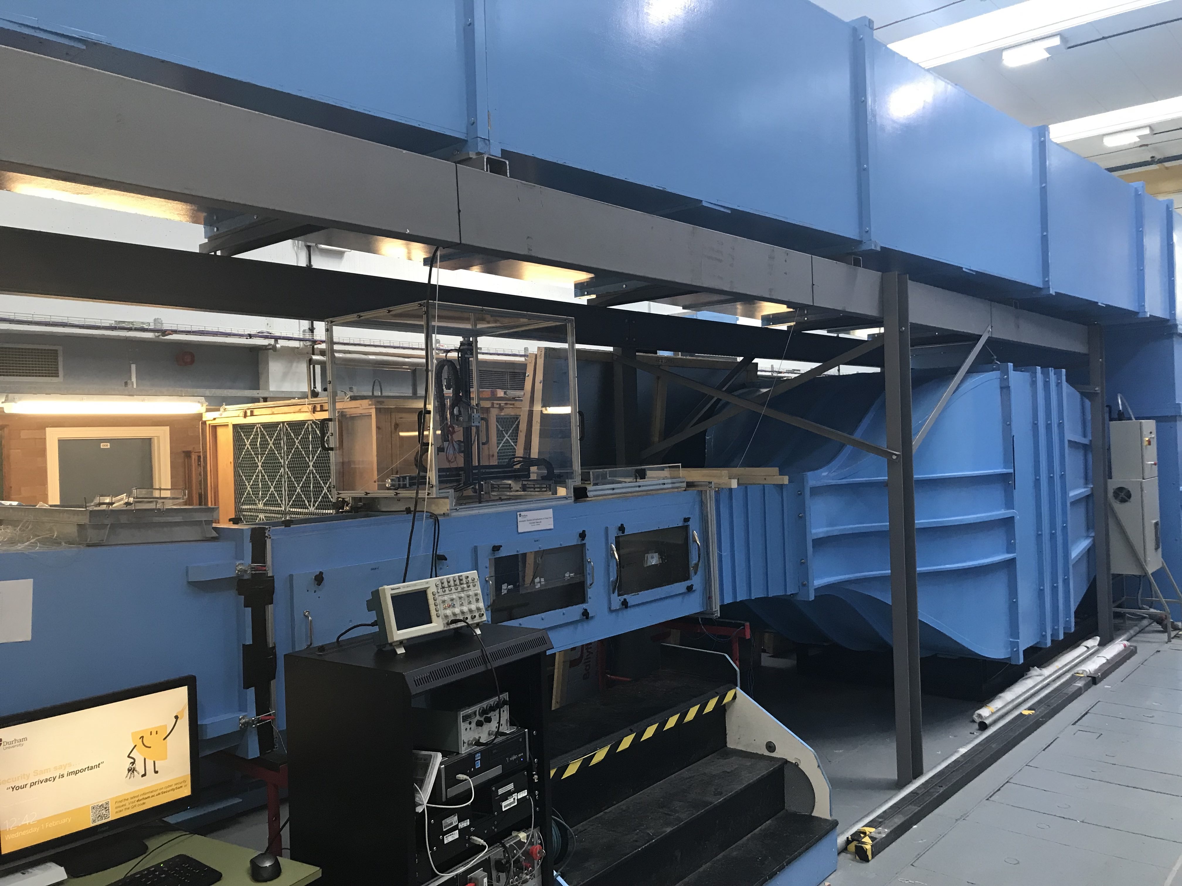
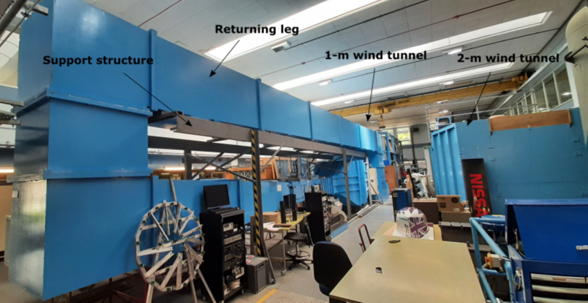
The Recirculating Wind Tunnel was repurposed from an open jet tunnel in 2023 to facilitate Particle Image Velocimetry (PIV) experiments and is the Department of Engineering’s second main facility for state-of-the-art turbulence and aerodynamics research. At the same time the screen and honeycomb were upgraded to provide a steady and low turbulence intensity of around 0.5%. Boundary layer growth in the test section is accounted for by a 0.1o in the flow direction along the test section length.
The wind tunnel is fitted with a 3-axis overhead probe traverse to accommodate multihole pressure probes and hot wires, alongside a 120mJ underfloor laser on a 2-axis traverse for PIV. Various pressure scanner options are available. The Durham Software for Wind Tunnels suite provides a full array of programmes for executing data acquisition.
Specifications:

Images:
Durham 2m Wind Tunnel
Contact: Professor David Sims-Williams
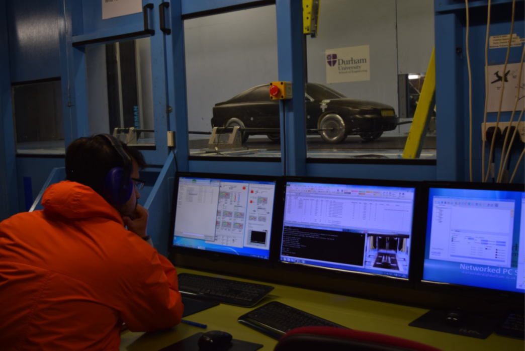
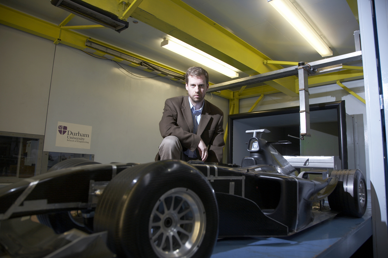
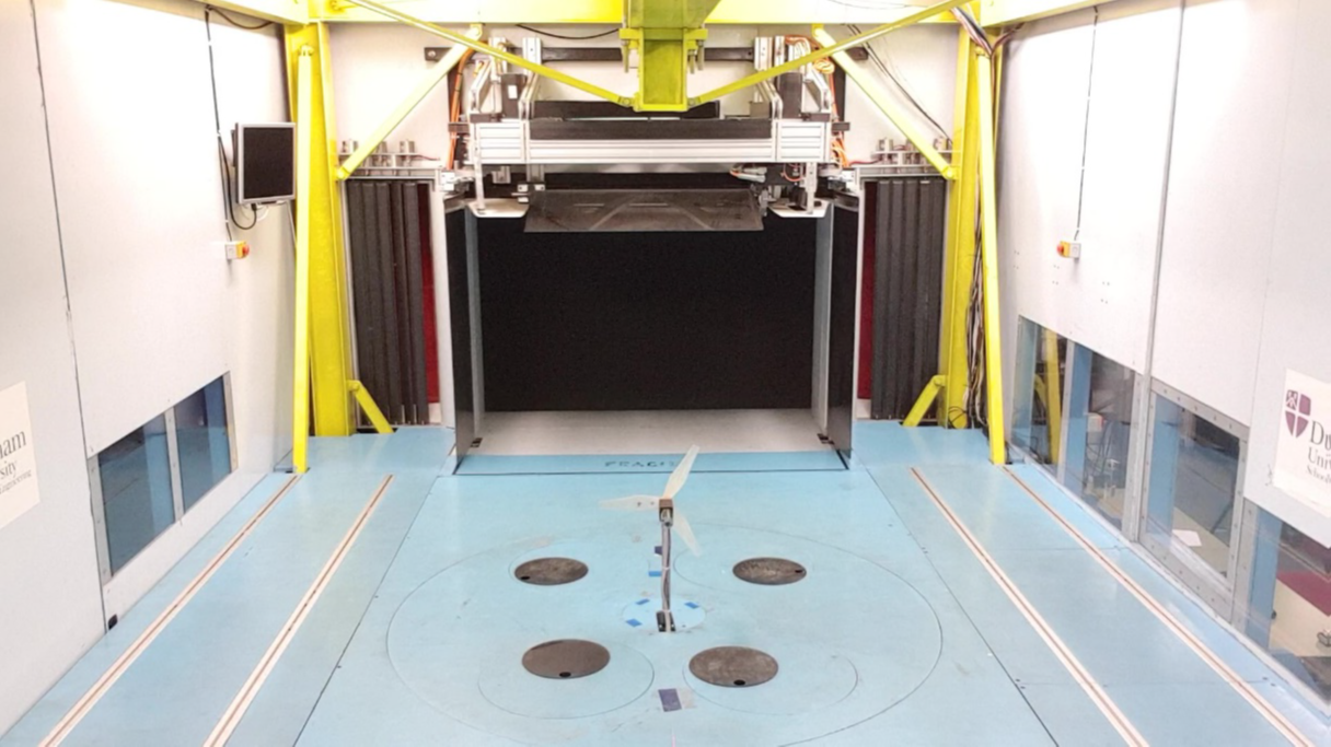
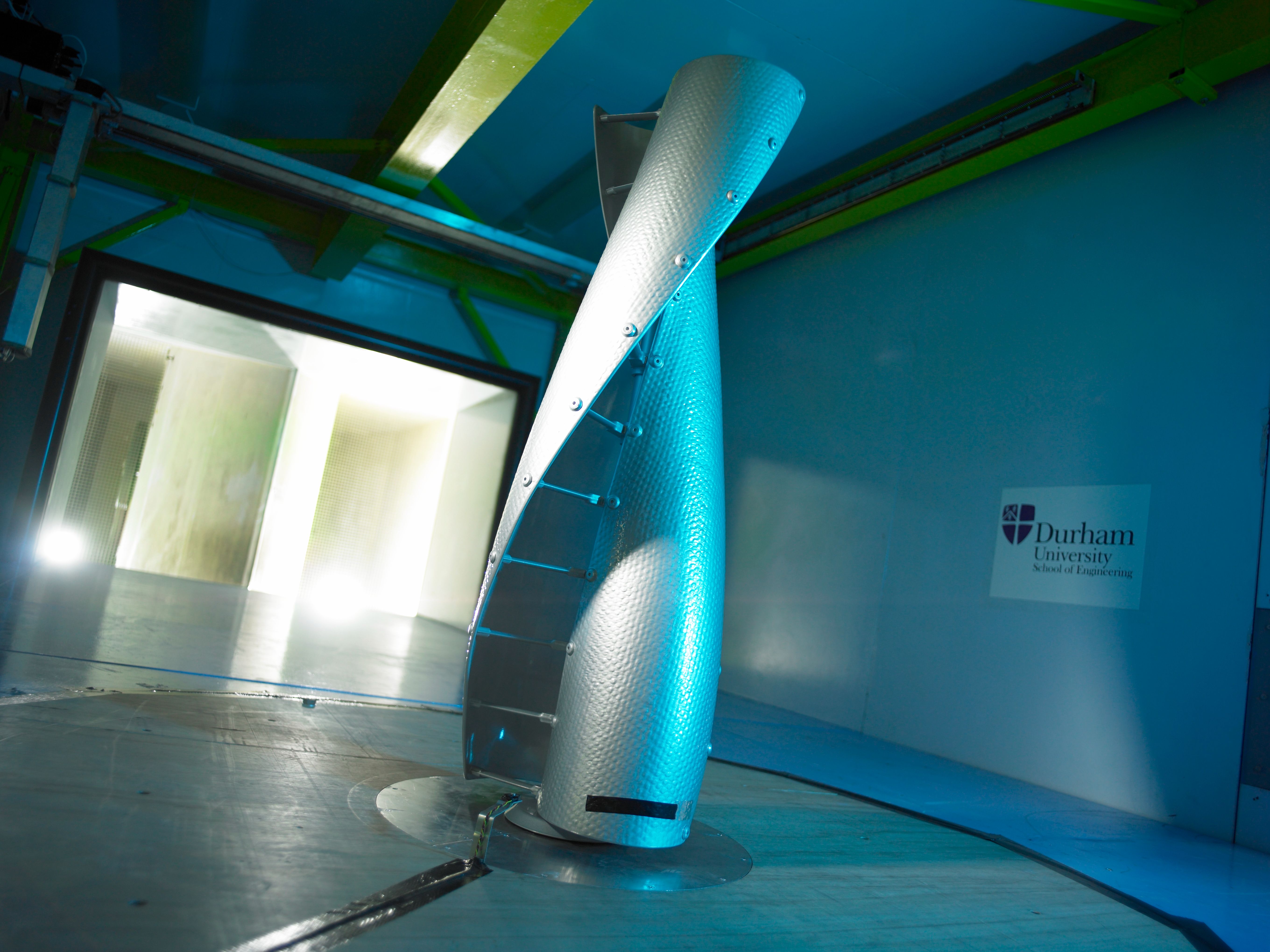
The Durham 2m Wind Tunnel is the main research wind tunnel facility at Durham University and is a member of the Subsonic Aerodynamic Testing Association (SATA). The wind turbine is of a ¾ Open Jet Eiffel-configuration.
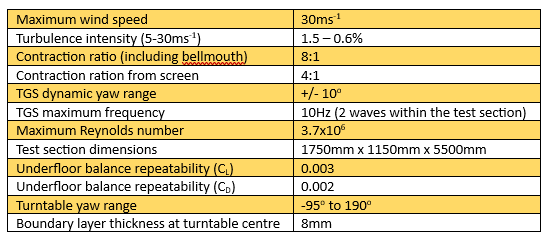
To replicate dynamic yaw conditions experienced by vehicles, the wind tunnel features a Turbulence Generation System (TGS) which can be programmed with a periodic waveform operation to represent on-road dynamic yaw probability densities. Dynamic inlet and outlet shutters are simultaneously operated to control jet/collector alignment. Horizontal and vertical turbulence components can be generated by foils in on both sides and the top of the nozzle.
The Durham 2m Wind Tunnel can be operated in one of two configurations:
- Fixed Ground:
This configuration consists of a turntable, of diameter 1650mm, with the centre 1.8m from the nozzle. Models are connected through the floor of the wind tunnel to an underfloor 6-component force balance which is rated to ±200N Drag, ±1000N Lift, ±400N Side force.
- Rolling road:
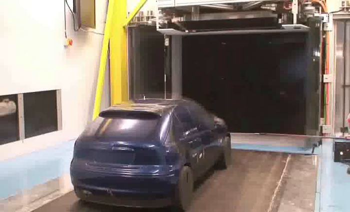
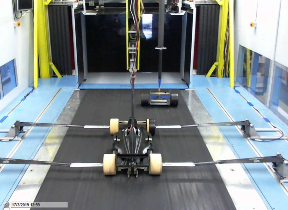
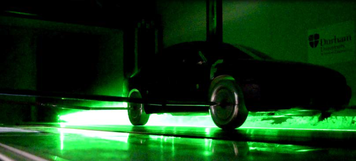
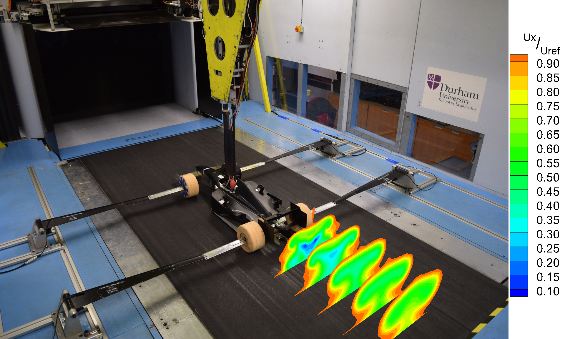
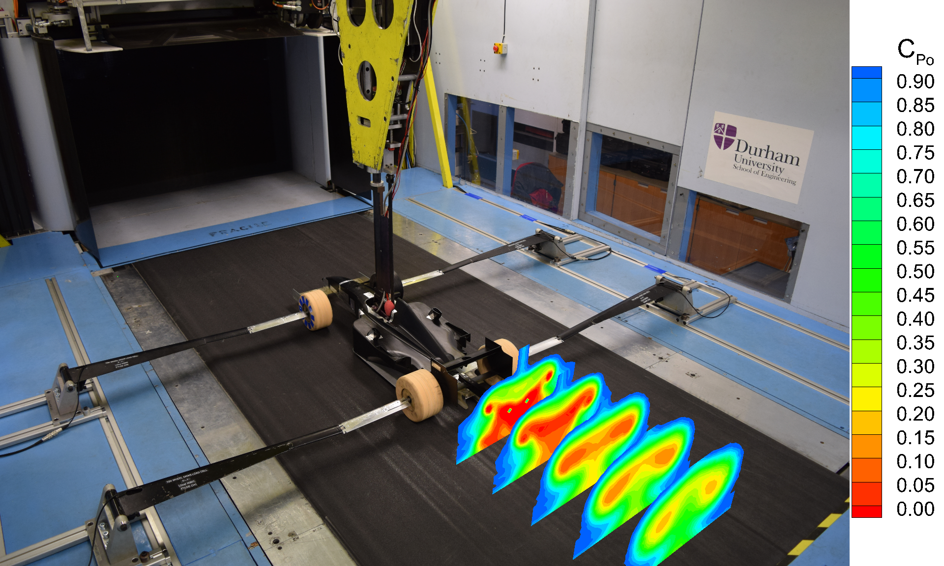
This configuration is optimised for the testing of road vehicles and features a belt which is 1.4m wide and 3.5m long, an overhead model motion system, and is complete with adjustable track, radius, and camber. Tests can be carried out with wheels on or off the track.
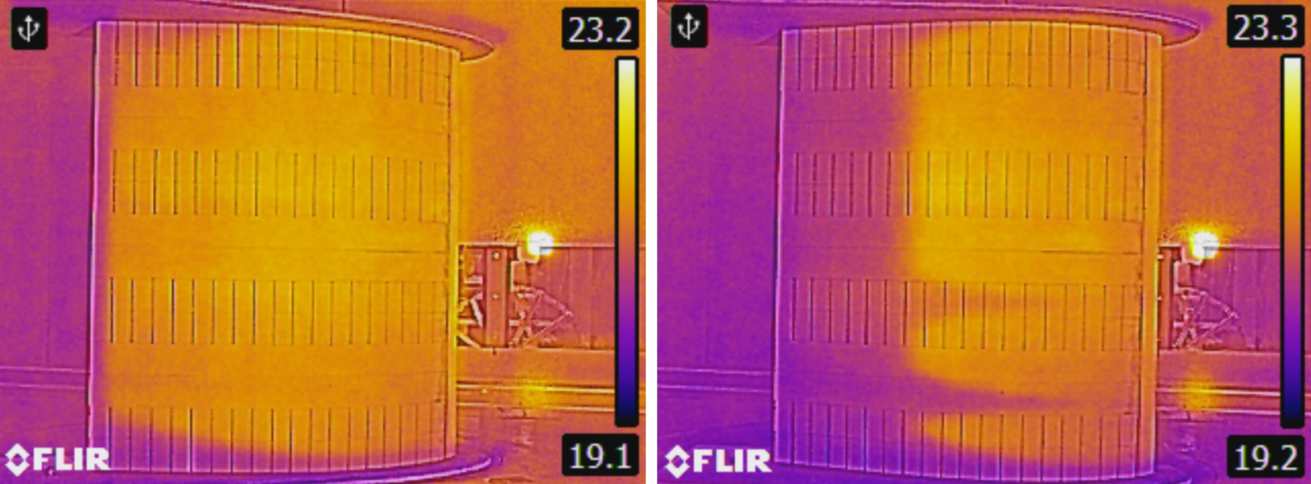
The tunnel is equipped with a 3-axis overhead probe traverse, suitable for multihole probes and hotwires, a 120mJ underfloor laser on a 2-axis traverse for PIV, an Artec White light scanner to record the geometry as tested, internal force balance options, and pressure scanning options, from individual transducers to 128 channel scanners. The facility is also suitable for conducting infrared thermography. The integrated Durham Software for Wind Tunnels allows full control of data acquisition programmes.
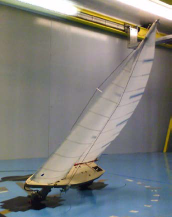
The multifunctional setup of the Durham 2m Wind Tunnel makes it suitable for a wide range of applications including 40% scale road vehicles, multi-vehicle scenarios, race cars, aircraft, wind turbines, and sailing vessels.
Specifications:
Images:
Durham Blowdown Facility and Rotating Test Rig
Contact: Professor Simon Hogg
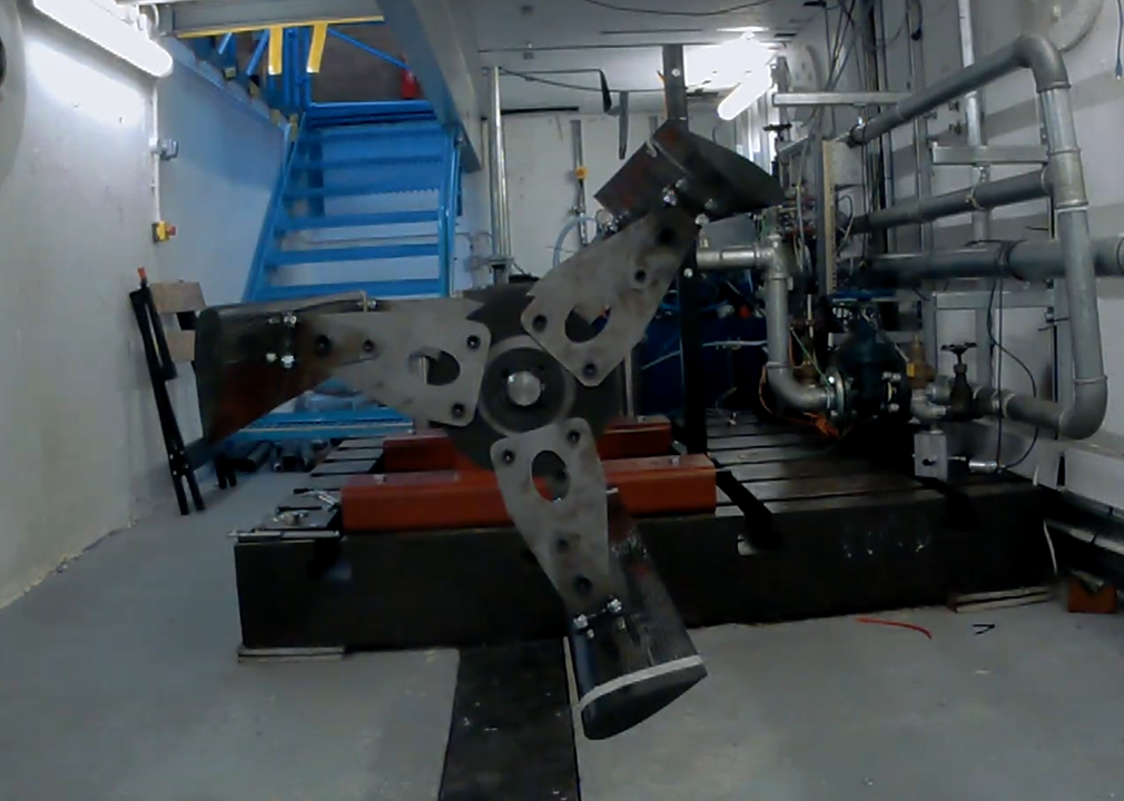
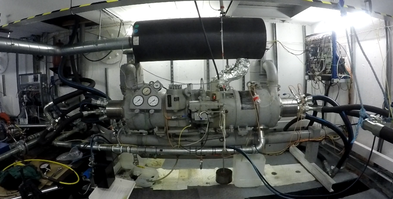
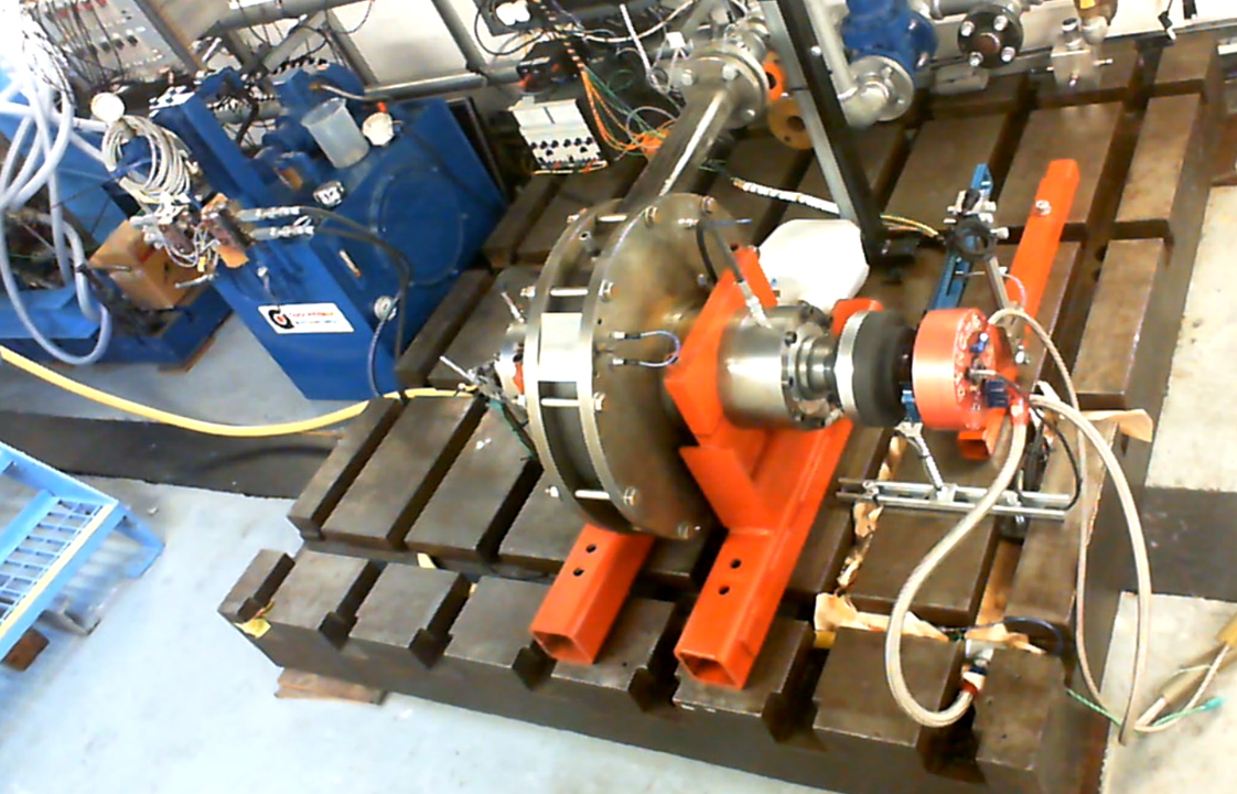
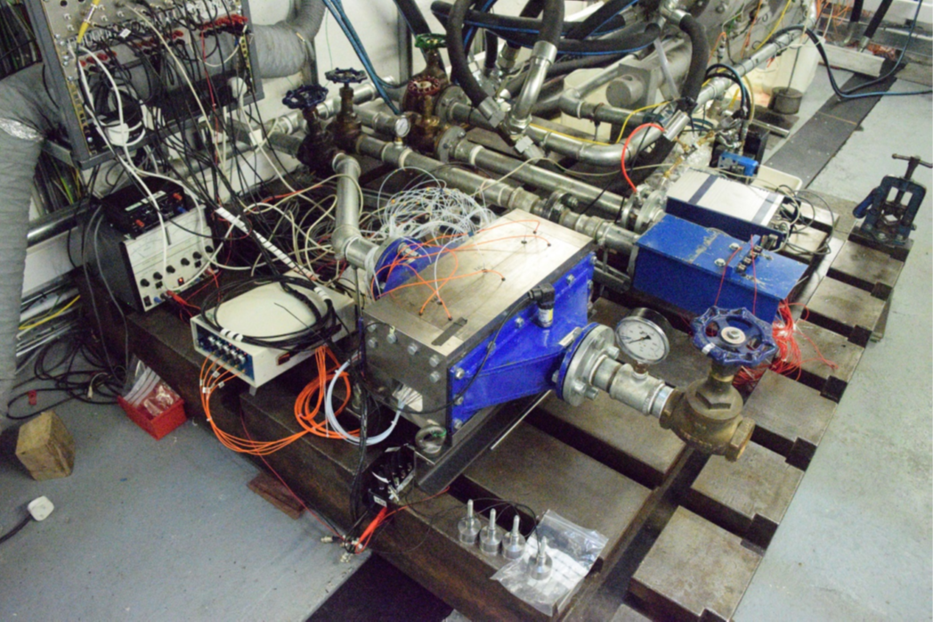
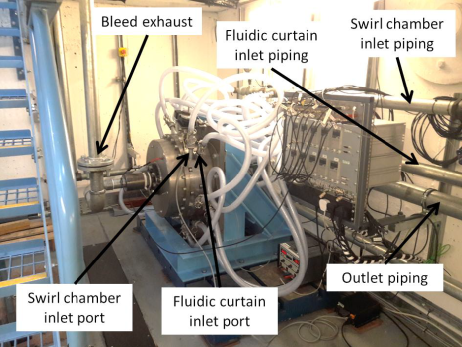
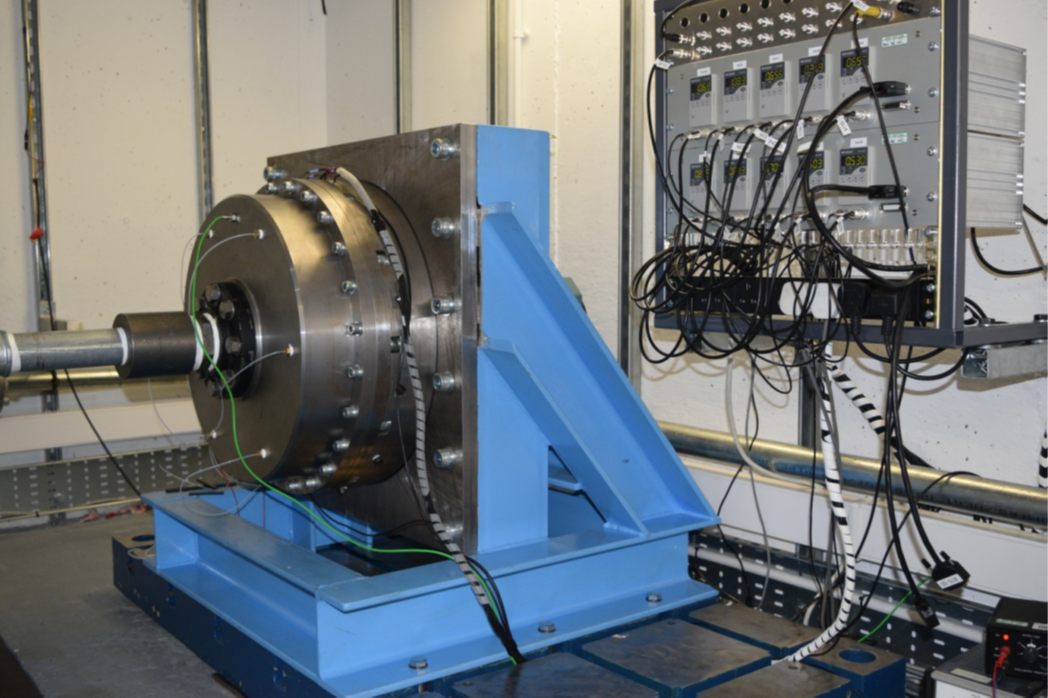
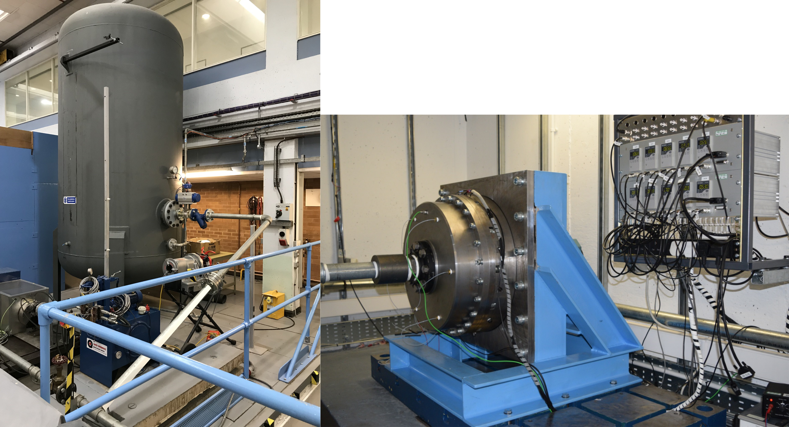
The Durham Blowdown Facility consists of a 10m3 air receiver, with a maximum operating pressure of 31 bar, which can deliver a maximum air speed of Mach 5 to several static and rotating test rigs. The test rigs are located in a hardened underfloor test cell with the pipework between the air tank and test cell designed in accordance with BS EN 10226:2005. The hardened test cell can be used independently of the blowdown facility for other high energy testing.
Data acquisition systems are linked to an external control station from which tests can be monitored. A selection of hardware, instrumentation and data acquisition is available for measuring:
- Air mass flow rate
- Temperature
- Pressure
- Forces via load cells
- Speed and displacement
Bespoke rigs have included static and rotating turbomachinery sealing test rigs for steam turbine and turbocharger applications, and prototype engine testing.
Images:
Durham Multifunctional Jet Generator
Contact: Associate Professor Lian Gan
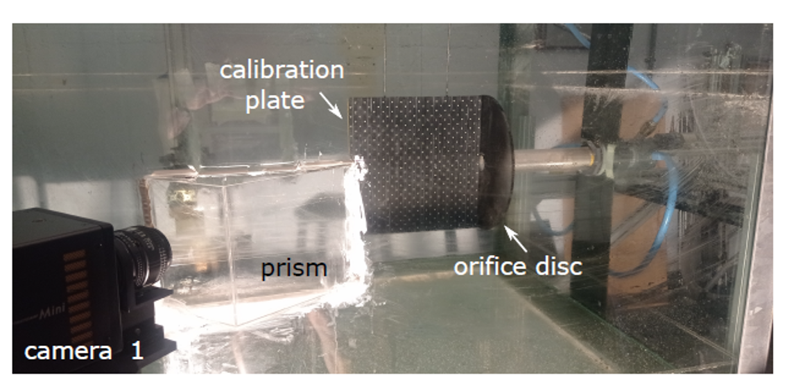
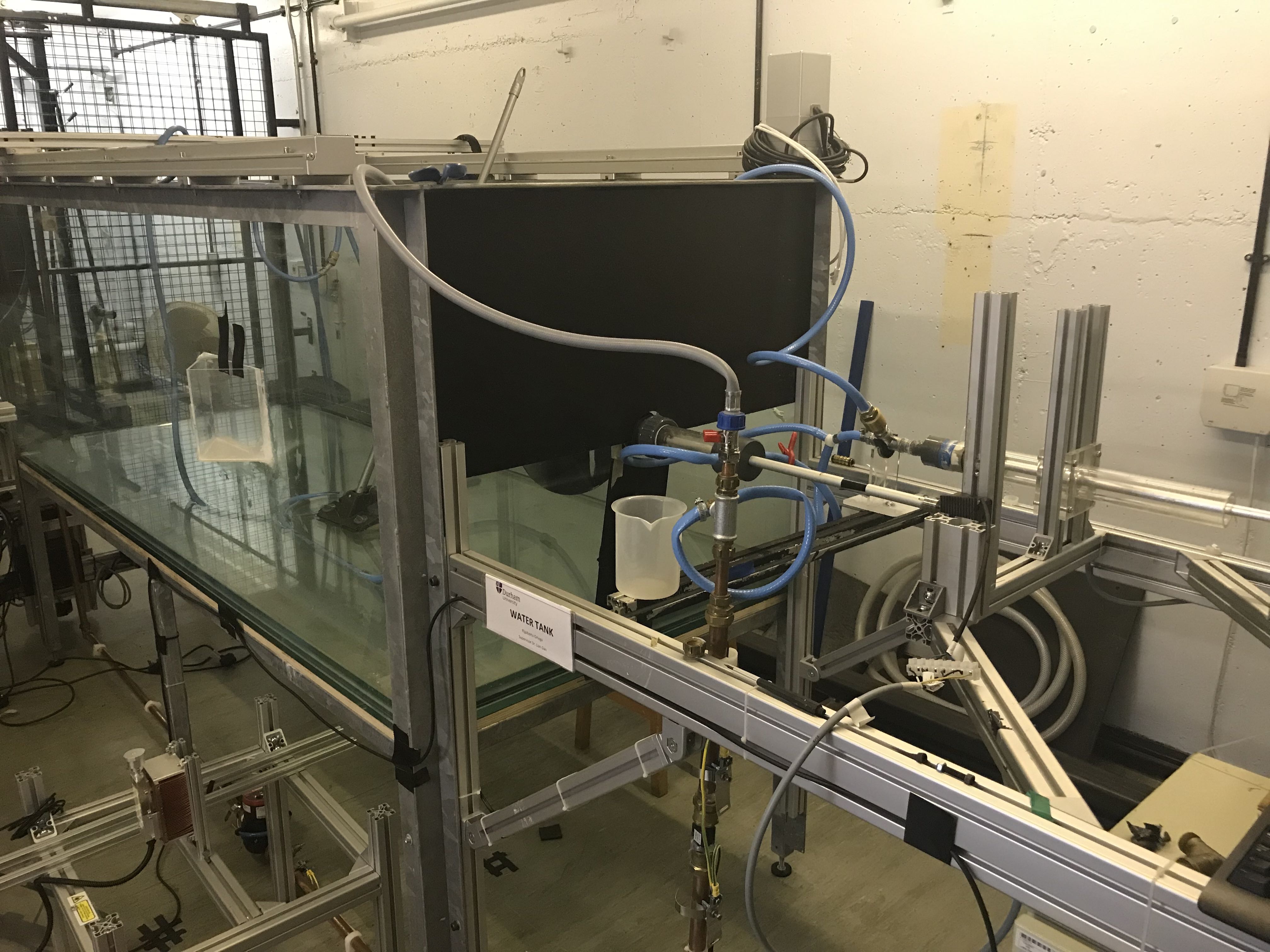
The Multifunctional Jet Generator is the only water-based facility in the Durham Engineering department and can be used either as a pulsatile jet generator or a continuous flow generator through programmable two axis simultaneous motion controls. The nozzle exit can be fitted with additively manufactured components to facilitate complex momentum delivery functions. A towing function is also available.
This facility is equipped with a 120mJ pulsed Newwave Solo Laser and a 5W CW laser, alongside 2 Photron Fastcam WX100 cameras and 2 PCO cameras for conducting a range of Particle Image Velocimetry (PIV) techniques:
- Planar Linear Induced Fluorescence (PLIF) for species concentration, mixture fraction, temperature measurements and scalar flow field visualisation.
- StereoPIV/TomoPIV for 3D velocity vector imaging from reconstruction of voxel intensities.
Specifications:

Images:
The Durham Cascade
Contact: Professor Grant Ingram
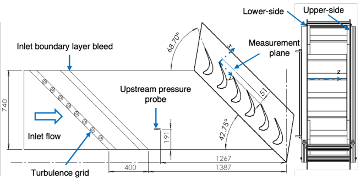
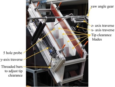
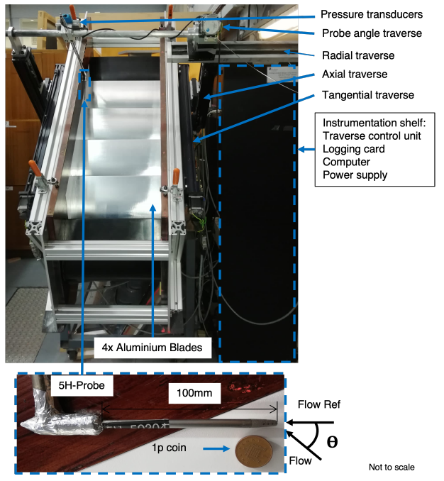
The Durham Cascade is a linear cascade consisting of six blades which have been modified to obtain a similar Reynolds number to the Rolls-Royce RB211 high pressure turbine blades. Reynolds similarity is achieved through a low speed, large scale design. Blades have been machined from aluminium to achieve high geometrical accuracy.
The Durham cascade is the primary tool for Secondary Flow research at Durham University and has been used for applications including optimising tip clearance and endwall profiling. Control of the inlet boundary layer is maintained by air bleeds to either side of the cascade, while the cascade is fitted with a 5-hole pneumatic probe on a 4-axis traversing gear to obtain full flow field information.
Specifications:

Images:
Durham Drum
Contact: Dr Lian Gan, collaborating with the Earth Sciences Department.
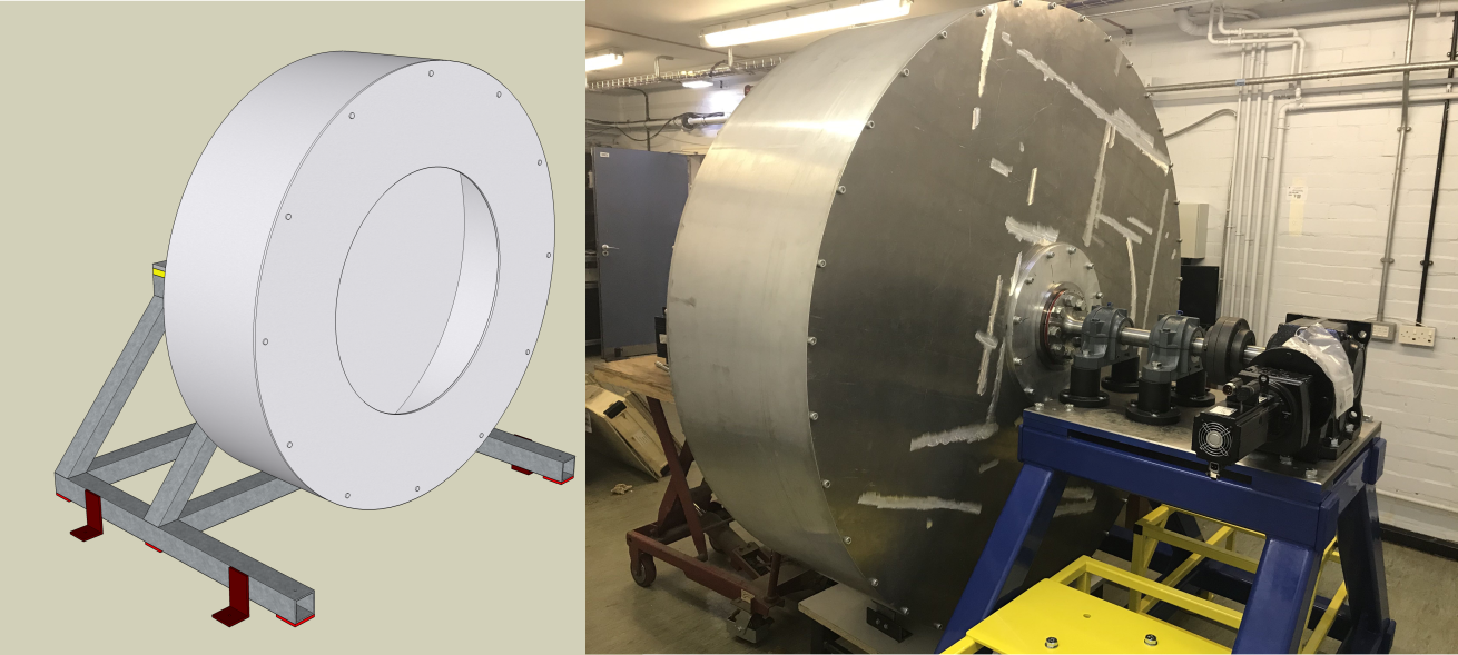
The unique 1.8m diameter, 0.5m wide drum system can be close-loop controlled, which has ultra steady rotating rate and can be in continuous operation up to a month at a time. Specifications:
- Speed range 10-4-102 rpm
- Speed accuracy < 0.1%
- Operating lifetime >5,000 hours
- Mass of loaded drum up to 700 kg
The drum system is also equipped a Renishaw RESR which has 0.008 arc second resolution, a laser profile scanner and a high speed high resolution Phantom LAB camera.
Images:


/prod01/prodbucket01/media/durham-university/departments-/engineering/74202-5112X1676.jpg)
/prod01/prodbucket01/media/durham-university/departments-/engineering/node-webpages/fm/facilities/RecircWT-external.png)
/prod01/prodbucket01/media/durham-university/departments-/engineering/node-webpages/fm/facilities/2mWT-car.png)
/prod01/prodbucket01/media/durham-university/departments-/engineering/node-webpages/fm/facilities/BlowDown_VAWT.png)
/prod01/prodbucket01/media/durham-university/departments-/engineering/node-webpages/fm/facilities/WaterTank-external.png)
/prod01/prodbucket01/media/durham-university/departments-/engineering/node-webpages/fm/facilities/cascade-annotated.png)
/prod01/prodbucket01/media/durham-university/departments-/engineering/node-webpages/fm/facilities/DurhamDrum.png)